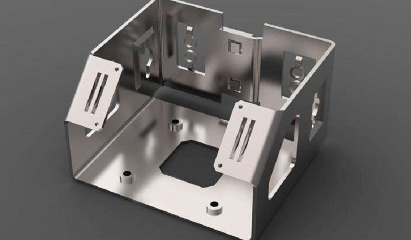
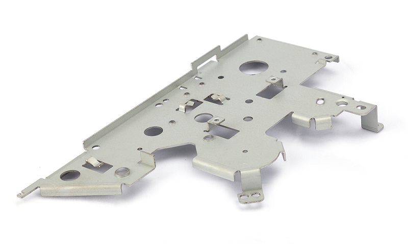
From the kitchen to transportation, we utilize a variety of mechanical and electrical gadgets daily to make our lives easier. The essential procedure is sheet metal design to make various components of such devices, which involves creating a virtual targeting piece prototype using hand drawing or CAD software.
Concept of sheet metal design
Any metal that can be converted into flat pieces as required thickness is called sheet metal. It is the essential element for manufacturing all mechanical systems and equipment. Some common metals used in manufacturing sheet metals are steel, aluminum, and copper. Sheet metal thickness is typically less than 6 mm, and a standard measurement system is used to categorize the thickness as a gauge, and it cannot be more than 30 gauge.

Designing the sheet metal refers to basic drawings or creating a virtual model of the required sheet metal product considering all designing parameters and tolerance. A sheet metal design is a blueprint that workers use to create the actual piece of any mechanical component or device using various manufacturing methods and tools.
Designing of sheet metal parts
Sheet metal parts are simple to manufacture with high-quality designs. The best aspect is that there are many different materials sheets to choose from to get the desired properties in the targeting parts, such as durability, strength, and conductivity.
Various phases are involved in creating a part from a sheet metal design, from choosing of material to finishing of the surface.
Material size and selection
Before beginning the design, select the material and its thickness based on their properties and your requirement.
- Aluminum: High strength, corrosion resistance, poor weld-ability,
- Stainless steel: High corrosion and temperature resistance, high strength-to-weight ratio
- Galvanized steel: high corrosive, less life, low cost
- Copper: Good thermal and electrical conductivity as well as high corrosive resistance
- Brass: High cold working capacity, good electrical and thermal conductivity.
Design parameters
Following are the parameters that need to be considered while working on sheet metal design;
- Bending radius
The radius of bending curvature of sheet metal when it bends is known as the bending radius, and the minimum bending radius is the smallest radius at which the sheet metal can be bent without causing any mechanical failure. Therefore, the bending radius should be at least equal to the thickness of the sheet.
While designing, a distance equal to two times of sheet thickness should be maintained between the Hole and bending edge to eliminate the risk of deformation.
- Bend height
Small bend height can cause deformation and low bending quality.
Bending height = 2 x sheet thickness + bending r radius
- Bent allowance
Bent allowance refers to the space between the bend line and the neutral axis.
Bent allowances = [Bent Angle in radian)] x [Bending Radius + (K-Factor x thickness)]

- Bend relief
Before bending, a small cut is made on the along-side surface to be bent, known as bend relief. It prevents bending surface distortion and ensures continuous bending. The depth cannot be less than the bending radius, and the relief width should be at least the same as sheet thickness.
- Hole diameter
Make holes of diameter equal to or greater than sheet thickness to avoid material failure around the hole during punching.
- K -Factor
It is the ratio of the neutral axis to the sheet thickness, which ranges from 0.3 to 0.6 based on the material characteristics and sheet thickness. You can use the K- factor chart to determine the correct value as your requirement.
- Flange width
While designing, maintain a flange width of at least four times the thickness of the sheet.
Flange width= 4 x thickness or more
The applications of sheet metal design
Sheet metal has been used in various industries, ranging from agriculture to aviation & space. Following are the Key sectors where sheet metal design has a crucial role.
- Agriculture industry
With the modernization of agriculture, various mechanical and digital equipment such as chemical kits, fenders, brackets, and sheet metal design is becoming increasingly crucial to manufacturing the equipment.
- Automotive industry
Sheet metal design is used to construct many parts of automobiles (other automotive machines), such as engine components, cylinders, and frames.
- Beverage industry
Almost all cans of various drinks and juice are made from sheet metal because it is easy to give shape for sheet.
- Electrical & Electronics
Sheet metal designs have a vast application in fabricating various components of almost all electronic and electrical devices, including frames, buttons, fans, LEDs, and more.
Sheet metal design with ZW3D CAD software
Computer Aid Design (CAD)of sheet metal for various applications can be created in ZW3D Software to proceed with manufacturing and assess the final product through simulations.
The best thing about this CAD/CAM software is that it allows sheet metal design with a specific tool named the “sheet metal” tab.

- Lofted Flange Design: Draw 2D of top and bottom view and click to Lofted Flange
- Bent cut:Design of bent cut in sheet metal can be achieved by Louver Design function of sheet metal tab.
- Punching patterns: The Dimple design feature can be used to create various punching patterns, such as holes, square cuts, guiding holes, boss-shaped holes, and others.
- Unfolding of design:The metal sheet design tab has an unfolding function that allows to unfold the final model and calculate various characteristics.
- Marking Bends: On clicking this function, it shows all the bends present in the CAD file transferred from other Software.
- Other functions of the ZW3D CAD software’s sheet metal design tab, such as change bend angles, change bend radius, set stationary face, and bend info, are also handy in designing.
Sheet metal design can also be performed using other CAD/CAM software like an Auto desk, solid works, CATIA V5, Creo, and more.
Mistakes to avoid when designing sheet metal parts
The following are some potential mistakes that a sheet metal designer should consider when creating a design.
- When transferring the CAD file for manufacturing, make sure the bending’s in sheet metal designs aren’t converted as folding.
- When designing a single metal sheet, use the same thickness for all parts.
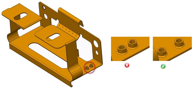
- Keep in mind that while designing sheet metal, such as cuts, holes, tabs, edges, fasteners, and other features are not too close to the bending position.
- Choose appropriate finishing based on whether the part needs to be protected or beautiful aesthetically. For example, Galvanization or Chromate Conversion are popular finishing for protection from corrosion and the external environment, and for aesthetics finishing, it’s based on required appearance.

- While designing the narrow U-shaped conduits in sheet metal, don’t use the width-to-height ratio lower than 2:1, resulting in low-quality bending and lowering sheet strength.
- Double-check the perpendicularity of corners
- Don’t employ unrealistic welding techniques like welding inside a box, heavy welding that can’t sustain the thickness of the sheet, or High-temperature welding can cause melting of the sheet.
- Please don’t make too many holes in the sheet since it will lose significant strength.
- Because the design is a virtual item, the designer must add hardware characteristics in the CAD design of sheet metal to create actual hardware.
- Identify the needs and consider the material properties listed below when selecting a material for sheet metal design.
- Strength
- Resistance to corrosion
- Manufacturability
- Toughness and elasticity
- electrical and thermal conductivity
Conclusion
Different agricultural, automotive, electronics, aviation, and other equipment components are constructed from sheet metal, so sheet metal design is crucial in the manufacturing industry. The selection of appropriate material that meets all requirements of the aiming product is the first and vital step in designing sheet metal. The design needs consideration of several factors like bending radius, bend height, bend relief, whole diameter, k-factor, bend allowance, etc.
Small mistakes like whole positions, welding requirements, Software related, and other design errors can affect the manufacturability and quality of the prepared design. The designer should consider the possible errors during the process to create the perfect product from design.


